Latest News & Updates

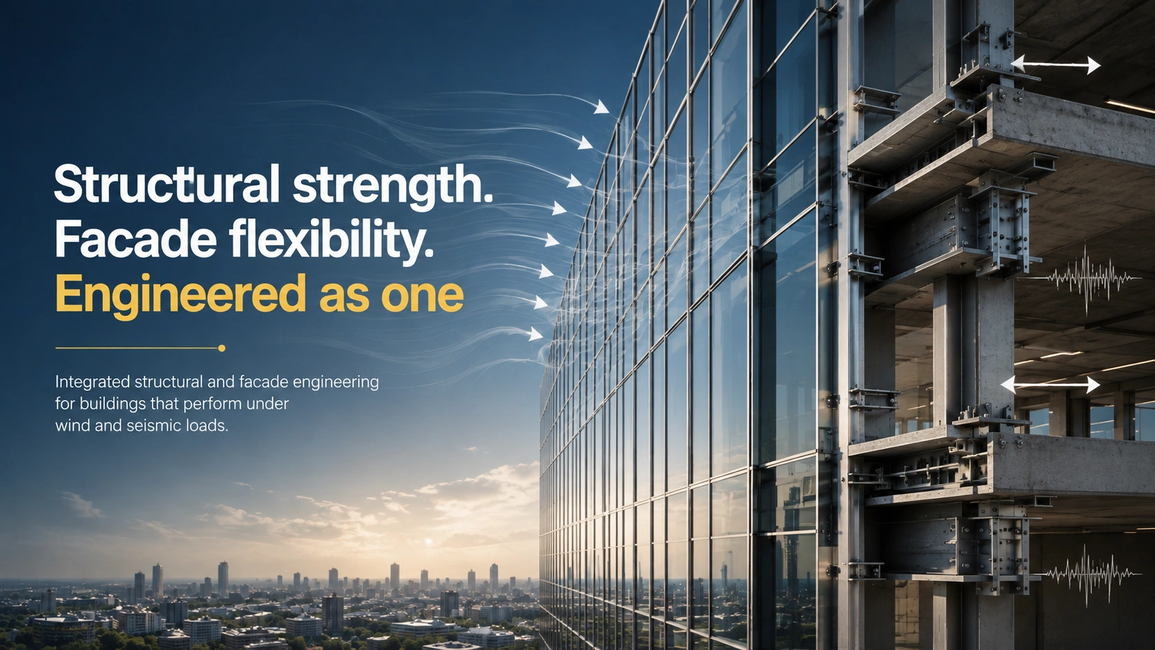
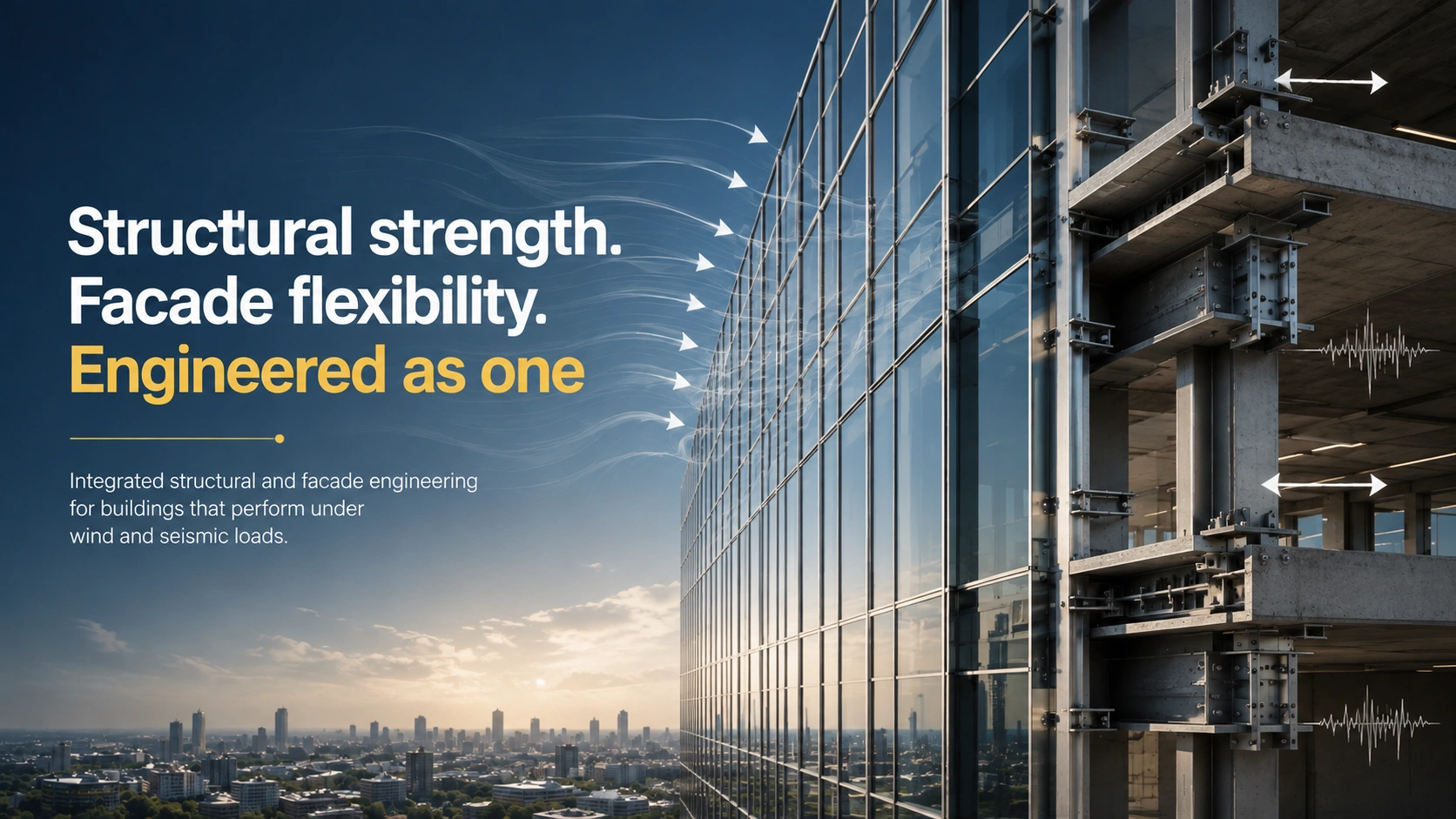
Wind and seismic loads influence far more than a building's structural frame. They also determine how the facade, curtain wall, glazing, cladding, and their connections must perform throughout the building's service life.
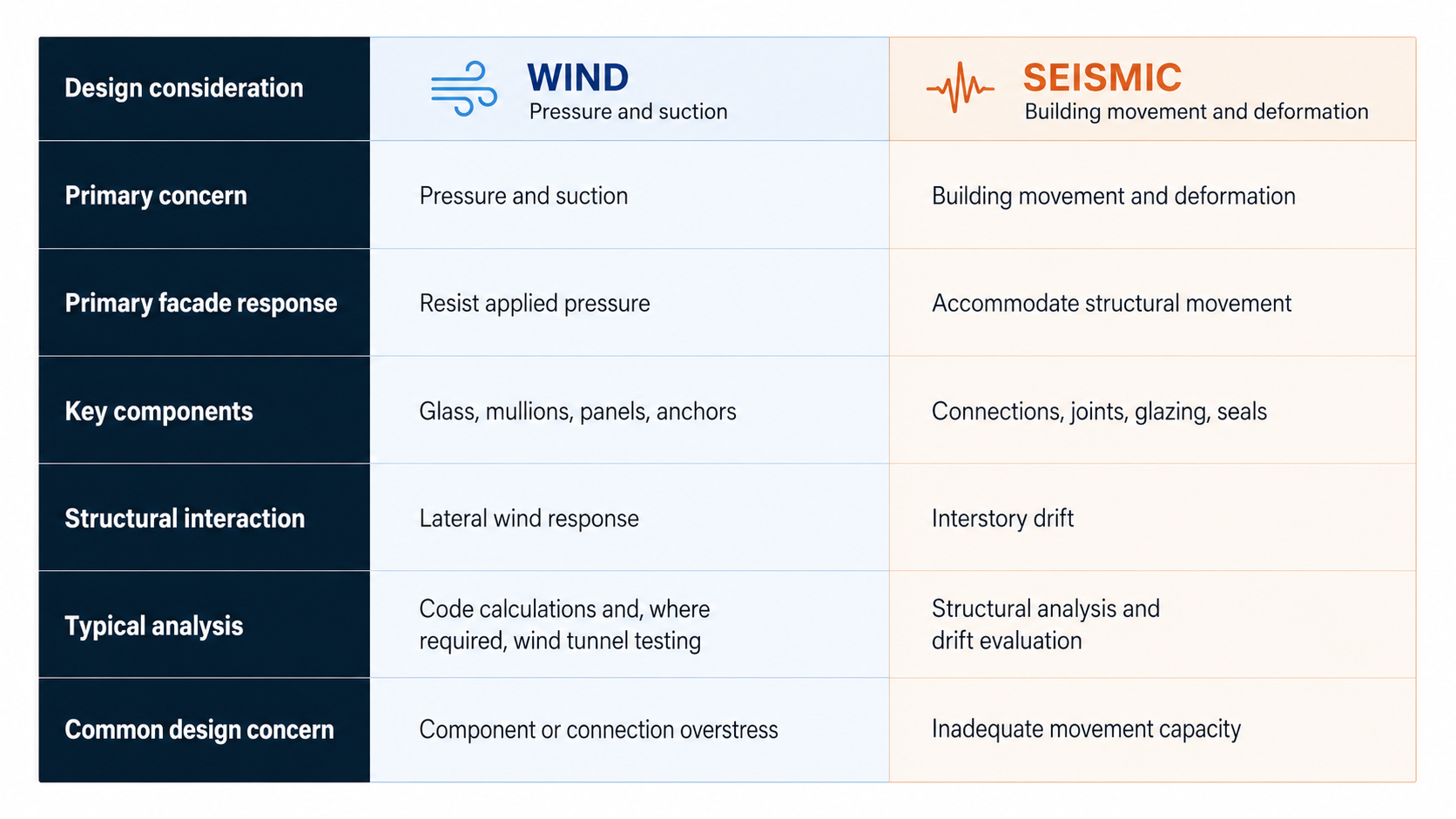
Wind places pressure and suction on the building envelope, while seismic events cause the structural frame to move and deform. The facade has to accommodate both without losing structural integrity, watertightness, or functionality.
In the U.S., structural loads are governed by ASCE 7-22, referenced by the 2024 IBC. Facade design also follows additional standards, including:
ASTM E1300 — Glass load resistance.
ASTM E330 — Structural performance of windows, doors, skylights, and curtain walls under uniform static air pressure.
Applicable aluminum and facade standards — Requirements for facade systems and components.
Structural analysis establishes the building's loads and movement, while facade engineering translates them into system, component, and connection requirements.
Wind load design begins with site-specific parameters established using the applicable provisions of ASCE 7-22. Basic wind speed is only one part of the calculation. Engineers also consider factors such as:
Once these parameters are established, wind effects are evaluated for different parts of the building.
Two important design categories are:
C&C pressures can be particularly important for facade design because localized pressures near corners, edges, and roof zones can be substantially different from pressures on the middle of a wall.
For a curtain wall, the design does not stop at determining a pressure value. Engineers need to verify that the complete load path—from the exterior surface through the glazing, mullions, brackets, anchors, and finally into the structural frame—can resist the design demand.
Design category
What it addresses
Facade relevance
MWFRS — Main Wind Force Resisting System
The overall structural system, including moment frames, braced frames, and structural walls that resist wind-induced lateral forces.
Establishes how the building's primary structural system responds to wind loads.
C&C — Components and Cladding
Localized pressures acting on facade elements such as curtain wall panels, windows, cladding, and their connections.
Particularly important near corners, edges, and roof zones, where pressures can differ substantially from those at the middle of a wall.
For curtain wall design, determining the C&C pressure is only the starting point. Engineers also need to verify the complete load path:
Exterior surface → glazing/cladding → mullions → brackets → anchors → structural frame
Each part of this load path must be capable of transferring the design demand safely into the building's structural system.
For taller or geometrically complex buildings, code-based calculations may be supplemented by wind tunnel testing. A scale model can be used to evaluate site-specific pressure distributions, building response, and other aerodynamic effects.
The resulting pressure data can help establish facade design pressures for different zones of the building rather than applying a single generalized value across the entire envelope.
Curtain wall performance can then be evaluated through appropriate testing and engineering analysis. ASTM E330, for example, provides a test method for evaluating structural performance under uniform static air pressure, while ASTM E1300 provides procedures for determining the load resistance of glass.
Wind tunnel results can therefore inform both the building's lateral design and the pressure requirements for facade components.
At ISE, structural and facade engineering can be coordinated from the wind analysis stage onward, allowing structural response, facade pressures, and connection requirements to be considered together rather than treated as isolated design inputs.
Wind pressure on the facade ultimately has to reach the building's structural frame through a continuous load path.
A simplified load path is:
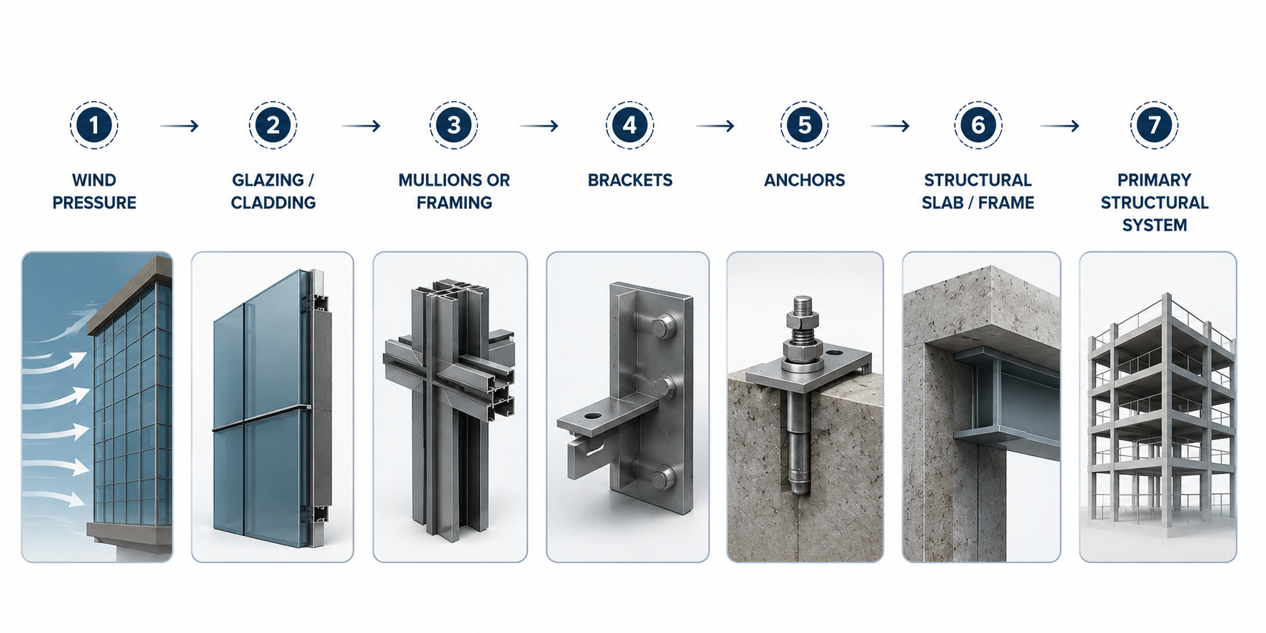
This makes facade connection design a critical interface between structural and facade engineering.
Common connection approaches include:
Cast-in channels can provide useful adjustment and load-transfer capabilities, but they need to be coordinated before concrete placement. This means facade connection requirements often need to be resolved well before detailed curtain wall installation.
Connections also need to accommodate construction tolerances, thermal movement, structural movement, and installation requirements. Slotted connections and adjustable brackets may be used where appropriate to allow the facade to align with the structure without unintentionally restraining building movement.
At floor lines, movement and stacking details need to be coordinated so that the curtain wall can accommodate expected vertical and lateral movement without transferring unintended loads between floors.
Wind design primarily addresses pressure, suction, and building response. Seismic design introduces a different challenge: movement and deformation of the building during an earthquake.
Seismic design begins with site-specific seismic hazard parameters, soil characteristics, building characteristics, and applicable code requirements. These inputs contribute to the building's seismic design criteria and, where applicable, its Seismic Design Category.
The structural system is then designed to provide the required strength, stiffness, ductility, and energy dissipation. The facade must accommodate the resulting building movement without compromising its performance.
During an earthquake, curtain walls and other facade systems may experience:
These movements can affect:
If the facade is too rigidly connected to a moving structural frame, the resulting restraint can cause glass breakage, connection distress, frame deformation, or failure of joints and seals.
Facade engineers therefore design appropriate movement capacity into the system through connection details, clearances, joints, and other mechanisms that allow the facade to accommodate expected structural movement.
Dynamic testing and project-specific performance requirements may also be used to verify facade behavior. AAMA 501.4, for example, provides a test method for evaluating static racking of storefronts, curtain walls, and related glazing systems under simulated building movement.
For critical facilities, facade performance can be especially important because maintaining enclosure integrity and limiting water intrusion may be part of the broader post-event performance objectives of the building.
Wind and seismic loads create different facade design demands. A facade may need to resist significant wind pressure while also accommodating seismic movement.
Facade anchors must transfer design loads while accommodating the movement and tolerances expected at each connection.
Depending on the project, engineers may need to evaluate:
A connection that is adequate for wind strength but prevents required seismic movement is not a successful facade connection. Conversely, a highly flexible connection still needs sufficient capacity to transfer design loads safely.
The objective is therefore not simply to design a stronger anchor. It is to design the right load path and movement behavior for the building.
Interstory drift is the relative horizontal displacement between two adjacent floors. While it is established through structural analysis, it directly affects facade design because each floor-to-floor connection must accommodate the expected movement.
Drift requirements can influence:
This is why drift requirements should be established early in facade development. Understanding structural movement before detailed facade design helps avoid late changes to connections, framing, and movement provisions.
There is no universal answer.
The governing design condition depends on factors including:
For example, buildings in hurricane-exposed regions may experience substantial wind demands, while buildings in high-seismic regions may require significant movement accommodation.
But geography alone does not determine the governing load. A project must be evaluated based on its site-specific design criteria and building characteristics.
Regardless of which load controls a particular component, the facade still needs to satisfy all applicable structural, movement, durability, and performance requirements.
Wind and seismic analysis only becomes useful when it translates into practical design decisions.
A coordinated engineering workflow typically involves:
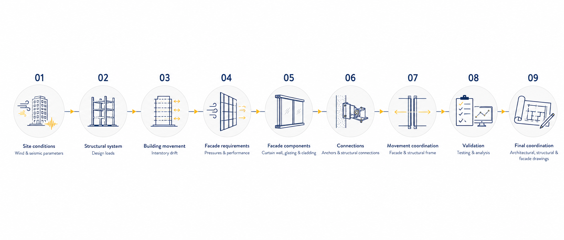
This approach helps reduce conflicts between the structural frame and building envelope before they become construction problems.
ISE provides structural engineering, facade engineering, and facade consulting as coordinated services rather than isolated design packages. Our work can include:
The objective is to translate structural loads and building movement into facade details that are practical, coordinated, and buildable.
Wind pressures, seismic demands, and structural drift only become meaningful when translated into buildable details—mullions, anchors, brackets, joints, glazing clearances, and connections that perform as intended.
For projects where structural and facade performance need to be resolved together from the early design stages, ISE can provide coordinated engineering support from schematic design through construction documentation.

.webp)